40th Anniversary Project – Torquing Bulldog Stage 2 – The Chasis
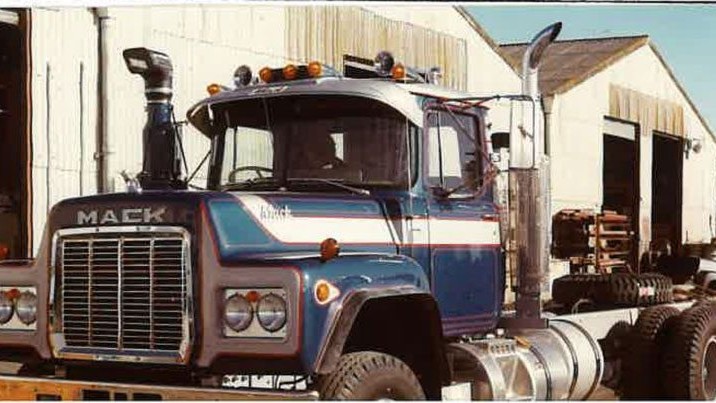
This month, we are assembling the chassis for Torquing Bulldog. At first it may seem straightforward, however, there is a minor twist that requires rectifying.
The chassis from the kitset is a good representation of your typical Mack R-model tractor unit, but this is where we hit a hurdle. Torquing Bulldog was a rigid bulk tipper, with longer frame rails to suit this application. Our task now is to match this chassis frame length in our build, and ensure the finished dimensions match the real truck as closely as possible.
The process of lengthening a chassis can be addressed in many ways. There is adding a piece of donor chassis to the rear of the existing frame and then repositioning the crossmembers. This is possibly less invasive than cutting the existing frame rails and stitching in a piece between the cut faces, but it can be a little more time consuming. The way we are going to approach this task is straightforward, with the finished result also adding strength and rigidity to our build, keeping in mind it will have to support a bulk tipper body once completed.
First, follow step eight of the instructions, gluing together 204 and 39 to parts 40 and 45. This step is important because you are laying out the backbone of the truck, and it is critical that care is applied to the assembly to ensure the chassis is straight and true to form. Once you are happy the frame is aligned, set it down to dry thoroughly, adding weight on top of the chassis to hold it in place as the glue sets if required. At this point, do not glue parts 46 to 51 in place; we will fit these later once the chassis has been stretched.

Next, jump to steps 9 and 10, and add the front suspension and steering axle. Once again we select only the parts we need to get the front steering axle locked in place – parts 52, 53, 66, 71 and 72. The reason for this basic installation of the front steering axle with no accessories is to give us a solid reference point to measure our overall wheelbase from. Allow the front axle assembly to dry thoroughly before starting the chassis lengthening stage.
The most important piece of information we need to lengthen the chassis is the as-built wheelbase of the real truck. The wheelbase is the measurement taken from the centre of the front steering axle back to the centre point of the suspension between the two drive axles. On an early Mack this is easy to locate as the Camelback style suspension of the time has an obvious centre pivot point. For us, there was a slight issue: Torquing Bulldog is no longer available to measure. However, we were extremely fortunate to be given a copy of the original Torquing Bulldog build sheets from 1994. They contained all the information we could wish for and more, and at the very top of the sheets was the magic number – an overall wheelbase of 223in. With this measurement we can do some mathematics and calculate the 1/25th scale version of 223in, which equates to 566.42cm. So, 566.42 divided by 25 equals 22.6cm, or 226mm – the 1/25th scale wheelbase for our model.
Laying the chassis out on a piece of paper, we can now mark the centre of the front axle. Then looking to the rear of the chassis, parts 43 and 44 form the main crossmember, and it is the seam where these two parts connect that reflects the centre pivot point of the Camelback suspension. The current wheelbase measurement between these points is 186mm. With a little more maths, the length we need to add to the chassis to achieve an exact representation of Torquing Bulldog at 1/25th scale is 40mm.
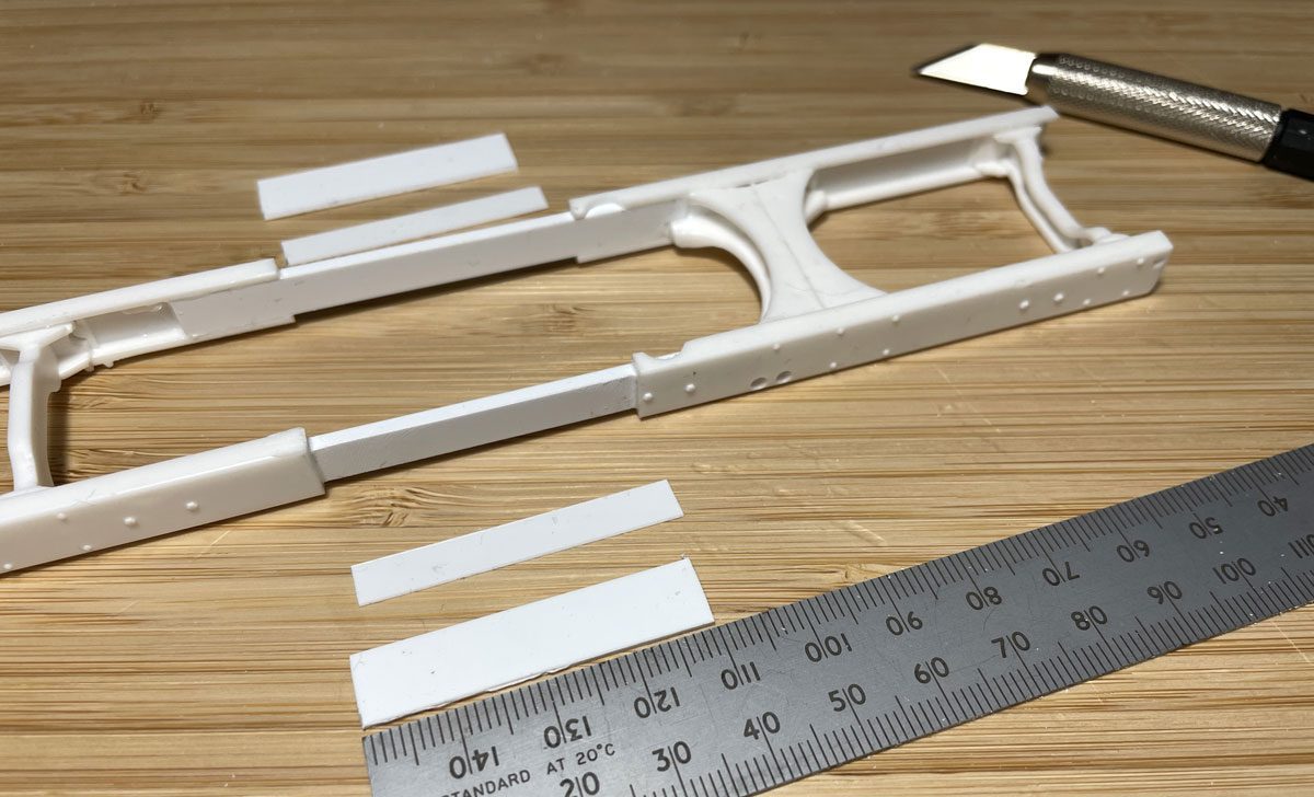
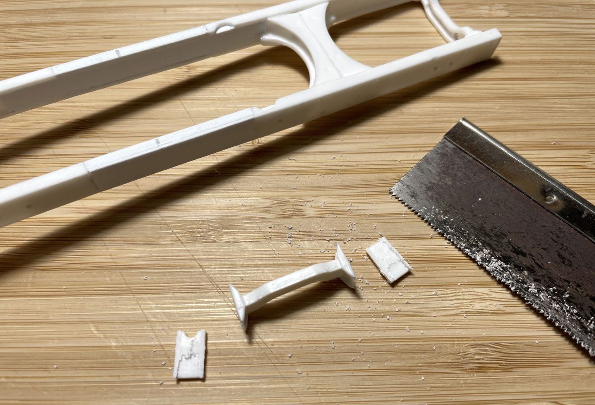
We can now start the process of splicing in the 40mm. Using our razor saw we want to first accurately cut the chassis in two. The best place to make this cut is 15mm in front of the main crossmember. By cutting here we have plenty of rail to apply the glue to, and bond the chassis to the splice, making a strong bond point between the two. Now cut two pieces of Evergreen #169 2mm x 6.3mm rectangle strip at 70mm long; this gives us the two required splices we are after, affording the 40mm of length we are looking to add plus 15mm each end to glue into the chassis rails.

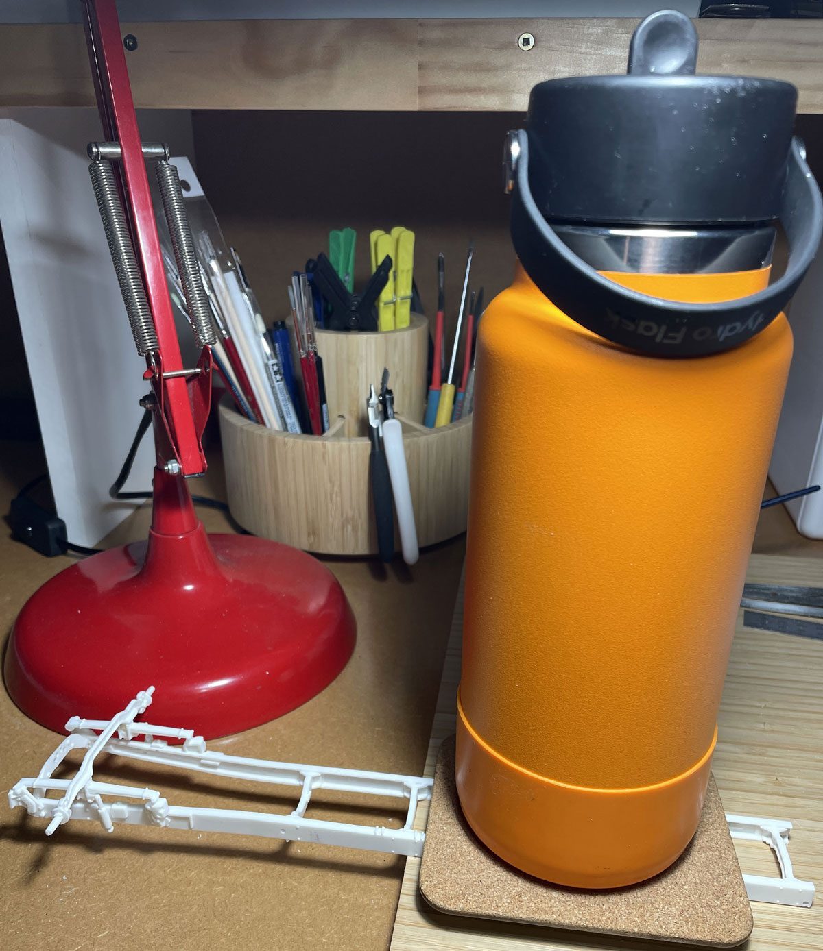
Clean all cut edges to ensure a tight fit, then apply glue to the contact surfaces and join the chassis and splices together. Accuracy is required here to set the chassis out flat on the work bench and ensure it is straight and true to form. Time spent here making sure this is spot on will save many headaches further down the track. With it sitting in place, apply weight if required as it dries thoroughly. Let it set at least overnight so it is well and truly locked in place.
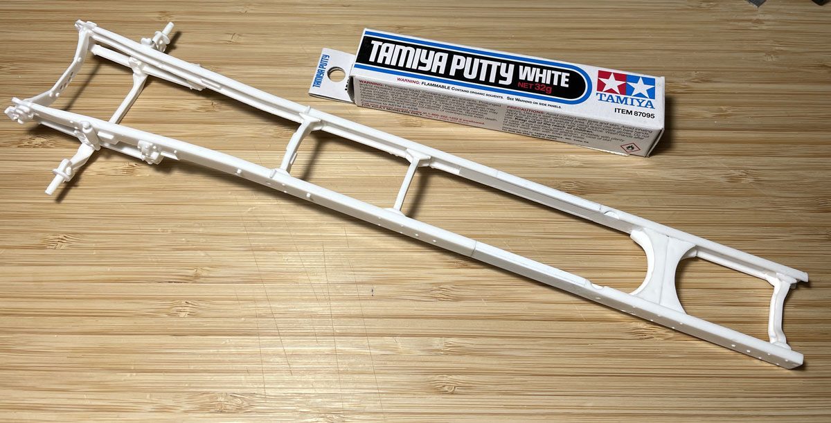
Chassis bonded together at the new length, we can add sheet styrene plastic to pad out the splice and match the gauge of the existing chassis rails. Cutt strips out of Evergreen 1.5mm sheet styrene plastic, shape to fit and glue in place. When the glue has cured thoroughly, use a fine file and fine sandpaper to blend the finished surfaces so they form a seamless joint. If you find there are small gaps, use Tamiya putty to fill these before you apply paint finishes later in the build.
With the frame stretched, an extra chassis crossmember is needed. You can either form one from scratch out of styrene plastic, or by hunting through the trusty box of spare parts you may find a candidate modifiable to suit. Glue this into place halfway between the two existing crossmembers, approximately at the 50mm mark.
At this point you can stand back and admire your handiwork. As I alluded to, there is more than one way to skin this cat, but given the fact we will have a bit of weight sitting on this build, adding the splices definitely adds much-needed strength and rigidity to our build. Next month we will add the diffs and chassis accessories.
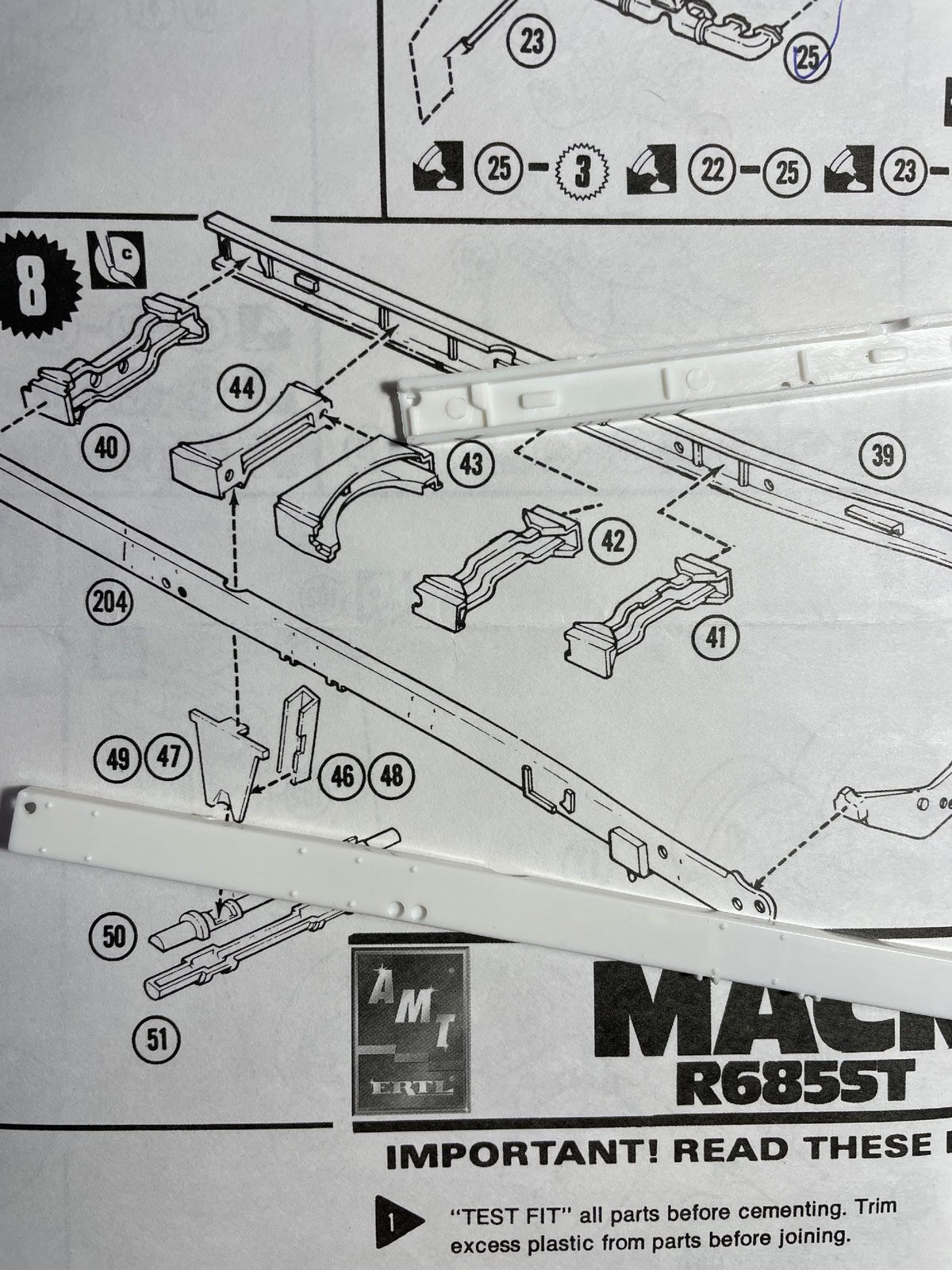
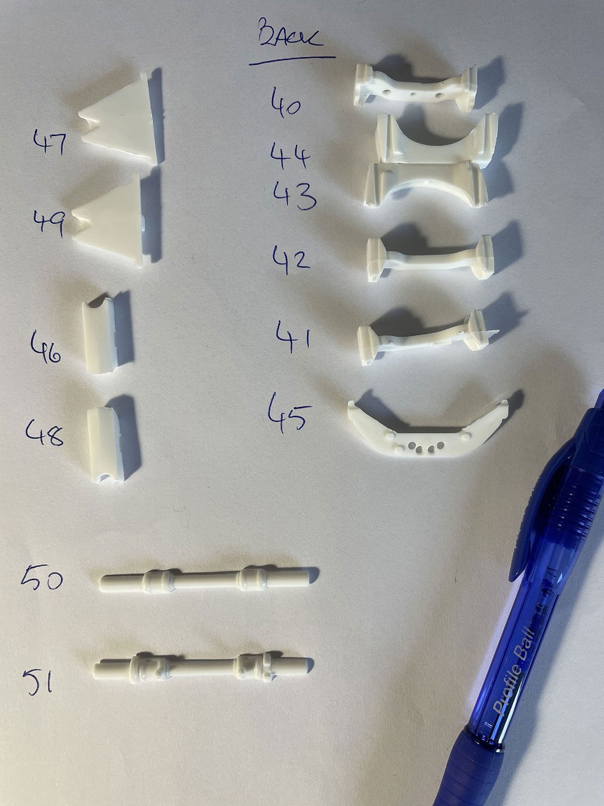
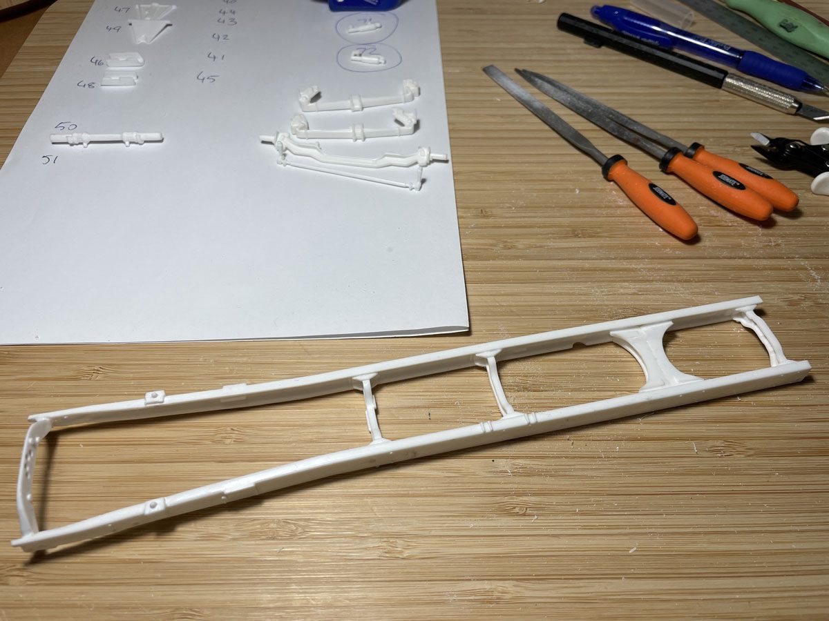
Laying out the required parts allows us to clean and prep them free of moulding lines and production flash, before assembly.
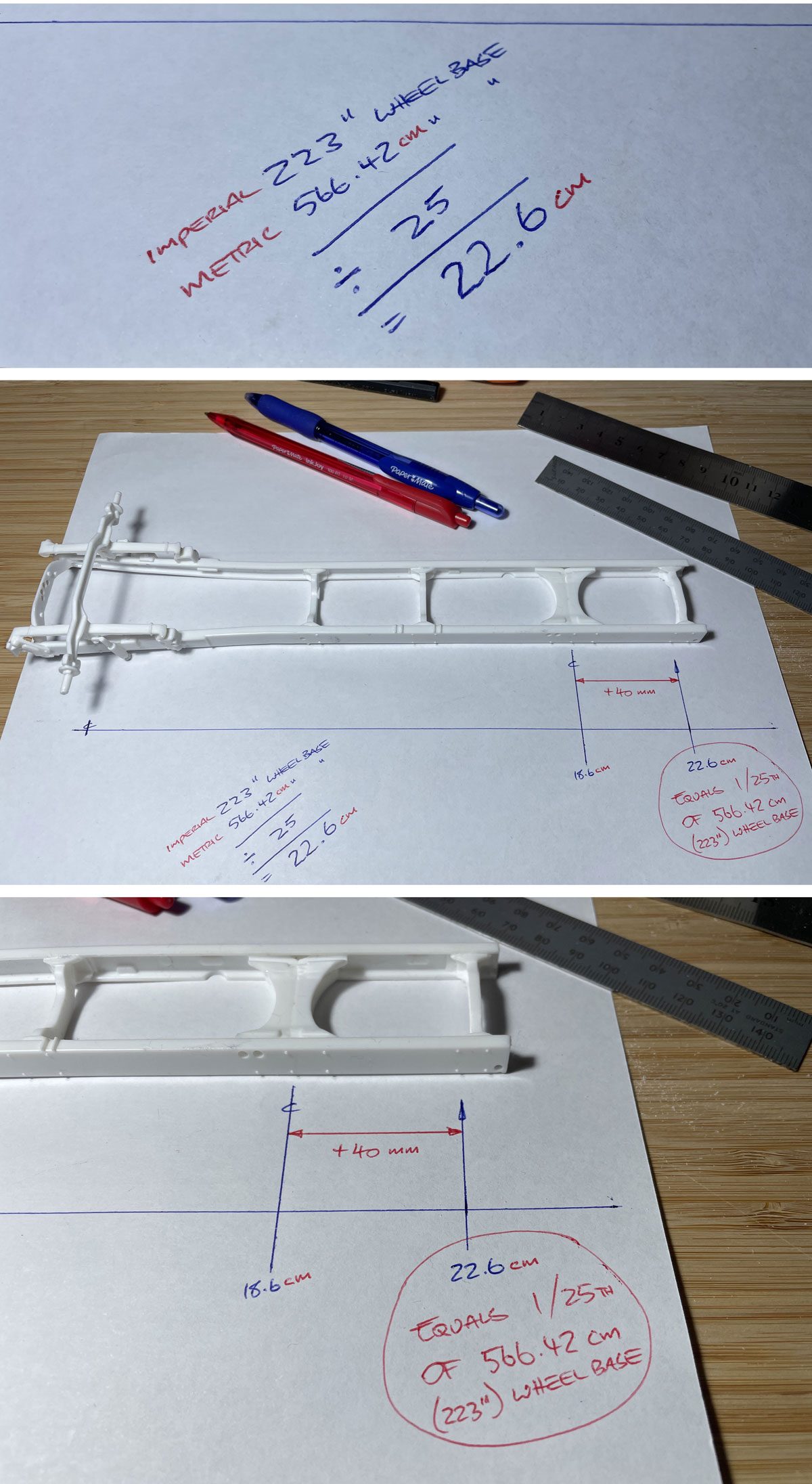
Armed with the magic measurement of 223in from the original build sheet, we can calculate in millimetres the exact measurement of the chassis splice required to take our build from tractor unit to rigid bulk tipper.
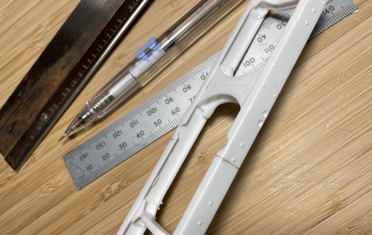
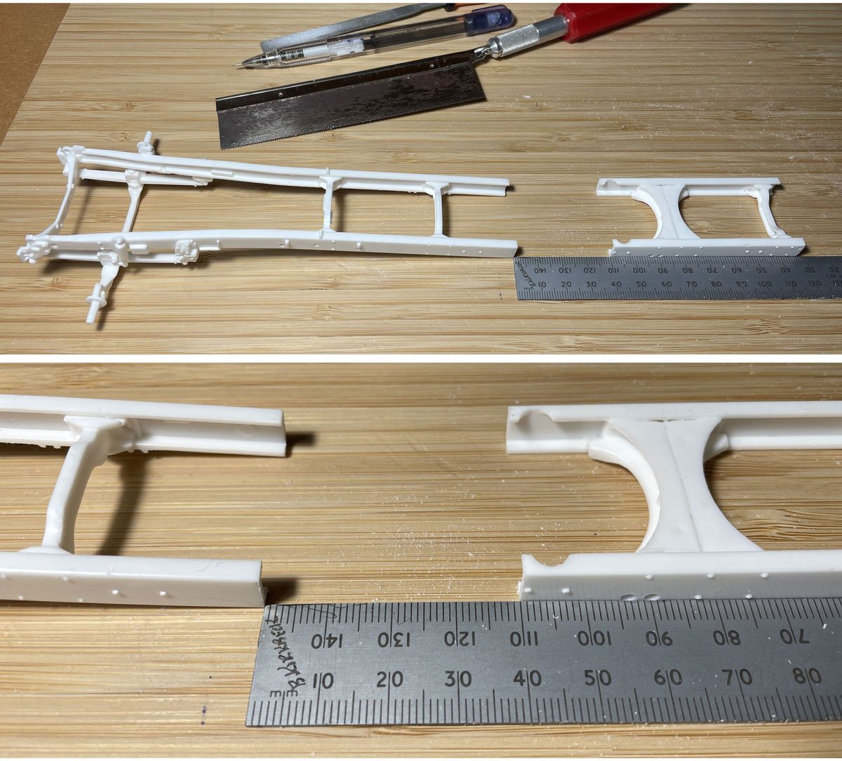
Mark in pencil the proposed cut line; allow 15mm of chassis in front of the main chassis crossmember (made up of parts 43 and 44); this will give you plenty of surface contact on the inside face of the chassis to glue the splice to. Use a wide blade razor saw and take your time to achieve a clean, straight cut.
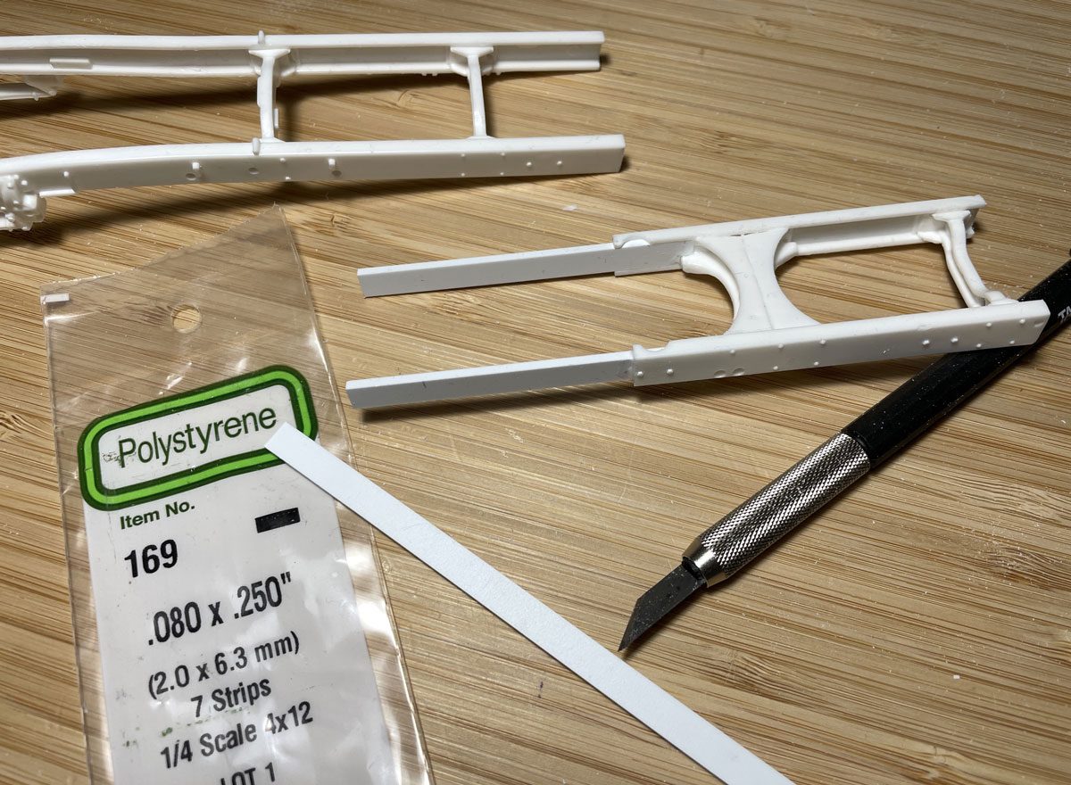
Cutting pieces of Evergreen #169 rectangle section to 70mm in length forms the splices we need to lengthen the chassis. Glue the splices into place between the front and rear sections of the chassis frame and apply a firm weight to the top of the chassis as it sets to ensure a true and correct-to-form result. Once thoroughly dry, cut Evergreen 1.5mm sheet styrene plastic into strips that cover the splices, and match the form of the existing chassis rails. If required, use Tamiya putty to fill any gaps or cracks in the joins.
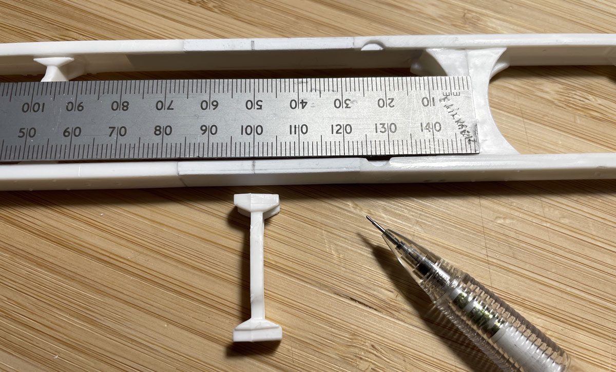
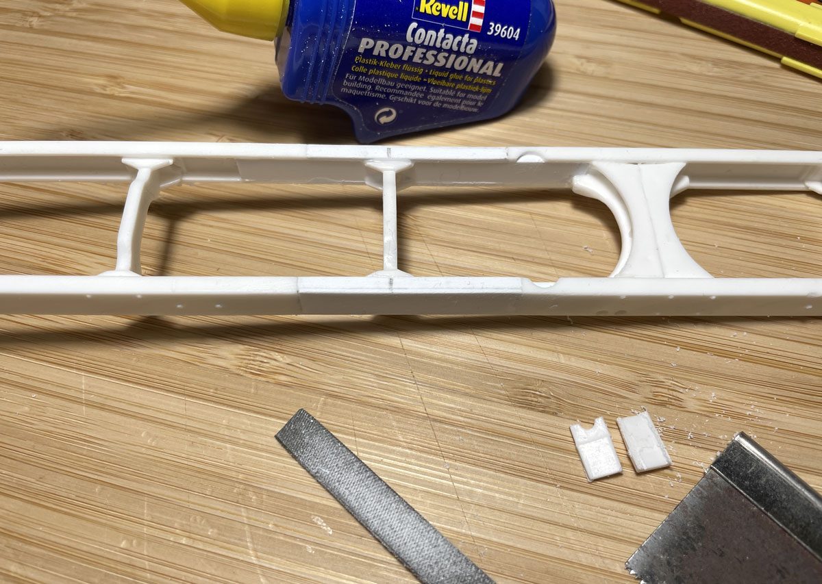
Now the chassis is extended to the required length for our build, add an extra crossmember into the chassis to strengthen that section of the frame. Form one out of Evergreen styrene plastic, or find a donor in the spare parts box. Locate the extra crossmember halfway between the two existing crossmembers.
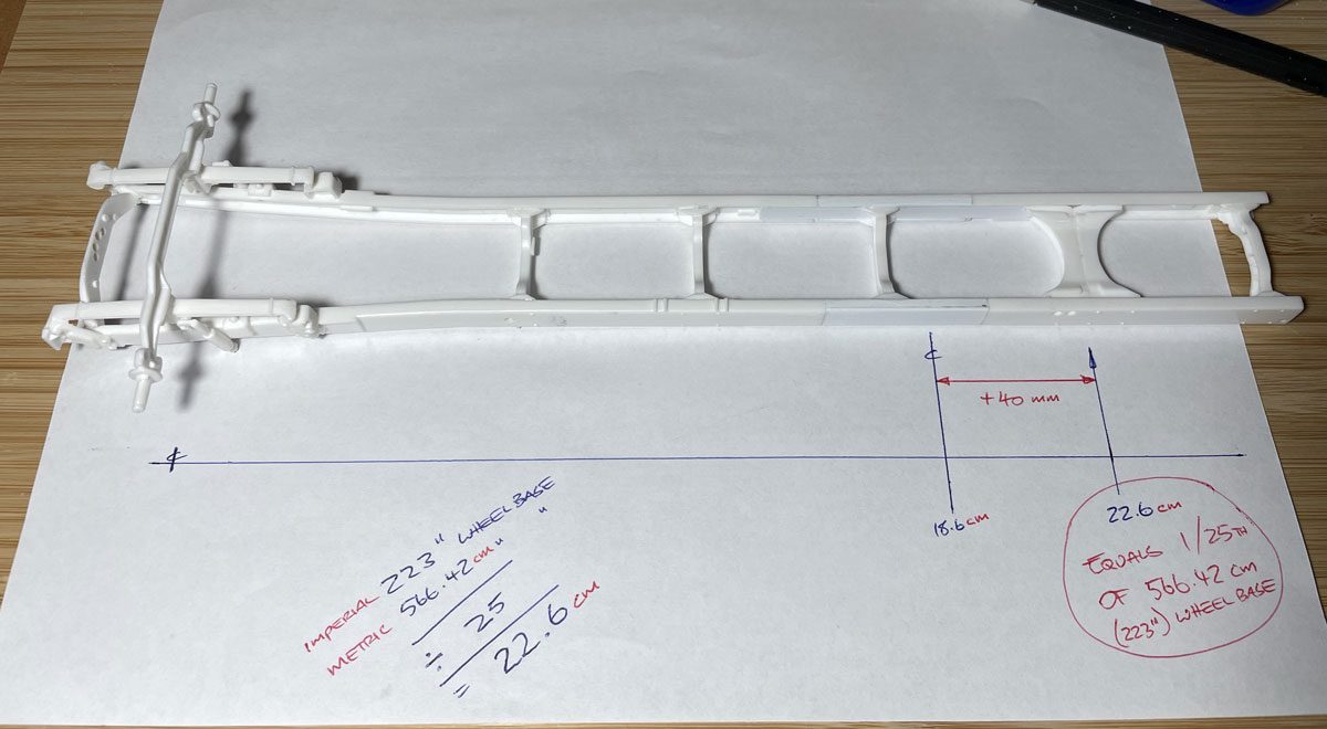
The completed chassis, now representing a 1/25th scale version of Torquing Bulldog’s 223in wheelbase.


